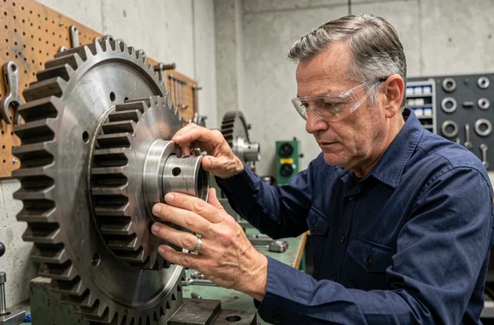
Circular motion and rotation describe two distinct kinematic realities, even though they share angular parameters (angular velocity, centripetal acceleration). The confusion between these two concepts persists because they use a common vocabulary, while they apply to different objects. Distinguishing circular trajectory and rotation around an axis is crucial for the correct modeling of a mechanical system, from the geostationary satellite to the automobile wheel.
Centripetal acceleration in uniform circular motion: a vector that changes everything
Uniform circular motion maintains a constant speed value, but the velocity vector changes direction at every moment. The resulting acceleration, called centripetal, always points towards the center of the trajectory.
This technical point is often misunderstood in many applied contexts. An object moving in a circle at constant speed is accelerated in the vector sense, even though its scalar speed does not vary. The distinction between the value and direction of the velocity vector is the foundation of any correct analysis of circular motion.
When the speed value varies in addition to its direction, we speak of non-uniform circular motion. The acceleration then has two components: a centripetal component (radial, towards the center) and a tangential component (along the trajectory). This is the case of a marble accelerating in a curved track or a centrifuge during ramp-up.
To properly understand the types of circular and rotational motion, it is essential to keep in mind that circular motion describes the trajectory of a point, not the overall behavior of a solid.
Rotation of a solid: axis, angle, and angular velocity
Rotation concerns an entire body that turns around an axis. Each point of the solid describes a circle centered on this axis, but the rotational motion is defined by global parameters: rotation angle, angular velocity, and angular acceleration.
A point located far from the axis travels a larger circle than a point close to it, but both share the same angular velocity. The linear speed, however, depends on the distance to the axis. A geostationary satellite describes a circular trajectory around the Earth without rotating on itself: its motion is circular, not rotational in the strict sense.
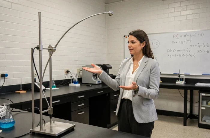
In contrast, a working drill illustrates pure rotation: the bit rotates around its axis, each point of the bit follows a circle, and the entire solid is in rotation. The Earth itself combines both: it rotates on its axis (rotation) and describes a nearly circular trajectory around the Sun (orbital circular motion).
Rolling without slipping: when translation and rotation coexist
Rolling without slipping is the most common case of coupling between translation and rotation. A car wheel moves forward (translation of the center) and rotates around its axle (rotation). The fundamental kinematic relationship links the center speed and angular speed: the center speed equals the product of the radius and angular speed.
The contact point between the wheel and the ground is, at the considered moment, stationary relative to the ground. This counterintuitive result directly arises from the superposition of the two motions. It explains why the tire adheres rather than slips.
- In rolling without slipping, the relationship between translational speed and angular speed is strict: changing one changes the other in the same proportions.
- As soon as there is slipping (sudden braking, skidding at startup), this relationship no longer holds and the two motions must be treated independently.
- The diagnosis of slipping in an industrial context (conveyors, printing rollers) relies on comparing measured linear speed and expected angular speed.
Rolling is a good test of understanding: it is neither reduced to translation nor to rotation. Correctly modeling a wheel requires simultaneously addressing both kinematics.
Applications in industrial maintenance and mechanical design
The distinction between circular motion and rotation has direct consequences for monitoring rotating machines. A rotating motor shaft generates vibrations whose fundamental frequency corresponds to its angular velocity. Vibration analysis exploits this relationship to detect imbalance, misalignment, or bearing wear.
We observe in applied mechanics that the confusion between the circular trajectory of a point and the rotation of an assembly leads to sizing errors. A gear, for example, transmits torque through rotation, but each tooth follows a trajectory that is not circular (it is epicycloidal or involute depending on the geometry). Reducing the motion of a gear to a simple circle distorts the calculation of contact stresses.
In design, the parameters to monitor differ depending on the type of motion:
- For circular motion (satellite, conical pendulum): trajectory radius, angular velocity, centripetal acceleration.
- For rotation (motor, turbine): moment of inertia, applied torque, angular velocity.
- For rolling (wheel, conveyor): non-slipping condition, ratio between linear speed and angular speed, coefficient of friction.

We find this classification in predictive monitoring: vibration sensors on rotating machines measure rotational parameters, while position sensors on a robotic arm track point circular trajectories.
Circular motion characterizes the trajectory of a point. Rotation characterizes the behavior of an entire solid around an axis. Rolling superimposes the two. Keeping these three categories well separated avoids modeling errors, whether the system studied is a satellite in orbit or a ball bearing in a gearbox.